
How Airflow Systems Are Designed in Small Electronic Devices
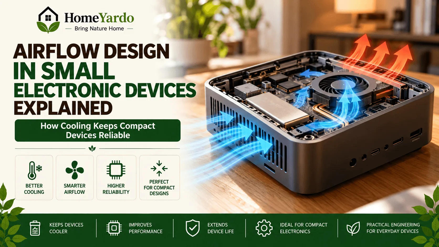
Small electronic devices have to fit batteries, circuit boards, sensors, power components, wiring, structural supports, and other hardware into increasingly compact enclosures. All of those parts compete for space, and many also produce heat while the device is operating.
That makes airflow an engineering consideration rather than simply a matter of adding a few openings to the housing.
A workable airflow system has to account for where air enters, how it moves around internal components, how much resistance it encounters, where heat is concentrated, and how air leaves the enclosure. Engineers may use natural convection, fans or blowers, conductive heat paths, or a combination of methods depending on the product.
The smaller the enclosure becomes, the more closely thermal management, component placement, vent design, and manufacturing constraints tend to interact.
Why Airflow Design Matters in Compact Electronic Devices
Airflow can affect both thermal performance and the operating conditions around internal components.
Processors, power electronics, batteries, charging circuits, motors, LEDs, and other components can release heat during operation. If that heat is not transferred away effectively, temperatures can rise around individual components or throughout the enclosure.
Good airflow design aims to move heat away from critical areas while avoiding unnecessary pressure losses and blocked passages.
This usually requires engineers to consider several factors together:
- Where the main heat sources are located
- How much heat the device is expected to generate
- The temperature limits of individual components
- Available inlet and exhaust area
- Internal obstructions
- Enclosure dimensions
- Expected ambient conditions
- Whether natural or forced airflow is practical
- Noise and power-consumption limits
Airflow is therefore only one part of the thermal system. Heat may also travel through circuit boards, heat spreaders, housings, thermal interface materials, and other conductive paths.
The Challenge of Designing Airflow in Limited Space

Compact electronics leave little unused room.
A battery may occupy a large part of the enclosure. A circuit board may sit only millimeters from the housing. Structural ribs, switches, ports, wiring, speakers, motors, or sensors can occupy the remaining gaps.
The engineer must create usable paths through that crowded interior.
Air Inlet and Outlet Placement
Vent placement affects the path air can take through an enclosure.
An inlet located close to an outlet may allow some air to bypass hotter components instead of traveling through the intended cooling path. Openings that are too restricted can also increase resistance to airflow.
Designers therefore look at both the size and position of openings.
Depending on the product, they may consider:
- Inlet area
- Exhaust area
- Vent geometry
- Screens or filters
- Distance between openings
- Nearby heat-producing components
- Orientation during normal use
There is no universal vent layout that works for every electronic device. The right arrangement depends on the internal architecture and thermal load.
Internal Airflow Pathways
Once air enters an enclosure, it needs somewhere useful to go.
Circuit boards, batteries, support structures, cables, and closely packed components can create restrictions. Sharp changes in direction can also increase pressure loss.
Engineers may rearrange parts or shape internal features so that air has a clearer route past components that need cooling.
In some products, relatively small layout changes can influence the resulting airflow considerably.
Component Positioning
Thermal design and component layout are closely related.
Placing several high-power components in one confined region can create a local hot spot even when the average temperature inside the device appears acceptable.
Designers may spread heat-producing components apart, move them closer to useful conductive surfaces, or position them where available airflow can reach them more effectively.
This is one reason airflow planning normally begins during product architecture rather than after every component position has already been fixed.
Heat Transfer Inside a Small Electronic Device
Cooling an electronic device does not depend on convection alone.
Heat can leave a component through several paths.
| Heat-transfer route | What happens |
|---|---|
| Conduction | Heat moves through solid materials such as the PCB, metal frame, heat spreader, or enclosure |
| Natural convection | Warm air rises and cooler air replaces it without a mechanical fan |
| Forced convection | A fan, blower, or another air-moving mechanism pushes air across components |
| Radiation | Heat is emitted from surfaces as thermal radiation |
Most real products use more than one of these mechanisms at the same time.
For that reason, an enclosure with limited airflow is not automatically poorly designed. Some compact devices rely more heavily on conduction through the chassis or other heat-spreading structures.
The engineering question is whether the complete thermal system keeps components within their required operating limits.
Passive vs Active Airflow
One of the main design decisions is whether air needs to be actively moved.
Passive Cooling
Passive cooling has no dedicated fan driving airflow through the enclosure.
Natural convection, conduction through the housing, heat spreaders, and carefully positioned vents may instead remove enough heat.
Passive designs can offer several advantages:
- No fan power consumption
- No fan noise
- Fewer moving parts
- Less internal space devoted to a fan
- Potentially simpler maintenance
The limitation is cooling capacity. Natural convection is generally less capable of removing large heat loads from a very compact space.
Active Cooling
Active cooling uses a fan, blower, pump, or another mechanism to increase heat transfer.
Forced airflow can move considerably more air across hot components than natural convection alone, allowing engineers to deal with higher heat loads.
It also introduces new design requirements.
A fan consumes power, produces noise, occupies space, and creates a pressure-flow relationship that must work with the resistance of the enclosure.
The fan itself therefore cannot be selected independently of the vents and internal airflow path.
Pressure Drop and Airflow Resistance
Moving air through an enclosure requires overcoming resistance.
Every vent, mesh, narrow passage, filter, bend, heat sink, and closely spaced component can contribute to pressure loss.
A larger fan does not automatically solve the problem. If the airflow path is highly restrictive, the actual operating airflow can be much lower than the fan’s unrestricted rating suggests.
Engineers consequently assess the complete air path rather than focusing only on nominal fan specifications.
Reducing unnecessary restrictions can sometimes improve cooling without increasing fan size or power consumption.
How Modern Airflow Systems Are Developed
Airflow development commonly moves through several stages.
The exact workflow depends on the product, budget, safety requirements, power density, and manufacturing process.
1. Establish Thermal Requirements
Before designing vents or choosing a fan, engineers need to understand what the system must handle.
This can include:
- Component power dissipation
- Maximum component temperatures
- Expected ambient temperature
- Device operating modes
- Duty cycle
- Available enclosure volume
- Noise limits
- Power budget
The highest-power operating condition often deserves particular attention because average use may not represent the most demanding thermal condition.
2. Map the Main Heat Sources
Not every part inside an electronic product generates the same amount of heat.
Engineers identify components most likely to influence thermal performance, such as processors, power regulators, charging circuits, batteries, motors, power transistors, or high-output LEDs.
That heat map helps determine where airflow or conductive heat paths may be needed most.
3. Plan the Air Path
Designers then consider how air can travel through the enclosure.
Ideally, incoming air reaches the regions that benefit most from cooling before it exits.
The design may involve:
- Dedicated inlet openings
- Exhaust vents
- Internal ducts
- Fan or blower placement
- Heat sinks
- Guides or baffles
- Gaps between circuit boards
- Conductive paths toward the enclosure
The objective is not necessarily maximum airflow everywhere. It is useful thermal management where it is required.
4. Use Simulation During Development
Computational fluid dynamics, commonly called CFD, can help engineers estimate airflow, pressure, and temperature patterns before committing to a final physical design.
A model may reveal:
- Recirculation zones
- Low-airflow areas
- Potential hot spots
- Excessive pressure losses
- Air bypassing important components
- Differences between alternative vent layouts
Simulation does not eliminate the need for physical testing. Its value is that engineers can compare design options earlier and reduce the number of changes required after tooling or manufacturing begins.
The same broad principle—planning airflow around the complete system rather than treating ventilation separately—can also be seen at a much larger scale in heat recovery ventilation systems used in buildings.
Why Housing Design Matters
The enclosure does more than give an electronic device its appearance.
It can act as part of the thermal system.
Housing geometry determines how much room is available around components, where vents can be placed, and whether heat can be conducted toward exterior surfaces.
A metal enclosure may provide different heat-spreading characteristics from a polymer enclosure. Yet material alone does not determine cooling performance.
Wall thickness, internal contact points, surface area, component placement, coatings, vent geometry, and the presence of thermal interface materials can all change how heat moves through the final assembly.
Dust, Water and Airflow Can Create Conflicting Requirements
Large openings may make airflow easier, but they may conflict with other product requirements.
An enclosure might also need protection against:
- Dust
- Water
- Accidental contact
- Electromagnetic interference
- Mechanical damage
Filters, meshes, membranes, seals, and smaller openings can provide protection, but they may also add airflow resistance.
Compact product engineering often involves balancing these competing requirements rather than optimizing a single parameter in isolation.
Airflow in Consumer Electronic Products
Many everyday products depend on carefully managed internal space, even when the airflow system is not visible from the outside.
Examples can include:
- Routers and network equipment
- Smart-home hubs
- Security cameras
- Small projectors
- Portable cooling products
- Battery chargers
- Compact computing equipment
- Handheld electronics
Homeowners increasingly use connected electronic devices such as cameras, sensors, hubs, and other smart-home hardware. Their exact thermal architecture varies by manufacturer, but compact housings still require designers to consider heat generation, component spacing, enclosure materials, and operating conditions.
Airflow-related design considerations also appear across other compact consumer products. Products marketed under names such as the beri crush vape and fifty bar show how manufacturers continue to package batteries, electronics, internal passages, and structural components within small housings.
The engineering principle is broader than any particular product: airflow and thermal requirements should be considered alongside the internal layout from the beginning of development.
Choosing Materials and Internal Components
Material selection affects mechanical design, manufacturing, electrical insulation, weight, durability, and thermal behavior.
Engineers may consider:
- Operating-temperature limits
- Thermal conductivity
- Structural strength
- Electrical properties
- Weight
- Manufacturability
- Assembly method
- Space available for thermal features
- Compatibility with neighboring components
Metal parts can sometimes help distribute heat away from concentrated sources, while polymers may provide benefits in weight, electrical insulation, cost, or manufacturing flexibility.
The correct choice depends on the complete product.
In compact products such as a beri crush vape, airflow is therefore best understood as one part of a larger enclosure and component-layout problem rather than as an isolated feature.
Testing and Improving Airflow Performance
Simulation provides predictions. Physical testing shows how the real assembly behaves.
Prototype testing is especially important because manufacturing tolerances, actual component behavior, surface contact, cable routing, seals, vent restrictions, and environmental conditions may differ from the model.
Airflow Measurement
Engineers can measure air velocity or flow rate at selected locations to determine whether air is moving as expected.
Measurements may also reveal that some regions receive less airflow than predicted.
Pressure Testing
Pressure measurements help identify restrictive areas in an airflow path.
If a fan or blower cannot overcome the resistance created by vents, filters, heat sinks, and internal channels, the resulting airflow may fall below the design target.
Thermal Testing
Temperature is measured at important components and locations while the product operates under defined conditions.
Depending on the project, testing may use:
- Thermocouples
- Temperature sensors
- Thermal cameras
- Data logging
- Environmental chambers
Engineers are usually interested not only in average enclosure temperature but also in localized hot spots and component junction-temperature limits.
Prototype Validation
A prototype may be tested under several operating states rather than one ideal condition.
Possible tests include:
- Normal use
- High workload
- Charging
- High ambient temperature
- Different product orientations
- Partially restricted vents
- Long-duration operation
The results can lead to changes in vent size, component spacing, fan control, materials, heat-spreading structures, or internal geometry.
Common Airflow Design Problems
Several issues appear repeatedly in compact electronic enclosures.
| Design problem | Possible result |
|---|---|
| Inlet and outlet too close together | Air may bypass hotter components |
| Internal parts blocking the path | Reduced airflow through important areas |
| Restrictive vents or filters | Higher pressure loss |
| Heat sources clustered together | Localized hot spots |
| Undersized fan or blower | Insufficient forced airflow |
| Poor fan placement | Recirculation or inefficient cooling |
| Thermal design added too late | Expensive enclosure or PCB redesign |
| Testing only average temperatures | Component-level hot spots may be missed |
These problems explain why thermal design is generally treated as a system-level engineering task.
Why Early Thermal Planning Can Reduce Redesign
Thermal problems become harder to fix once circuit-board dimensions, component positions, enclosure tooling, battery location, and industrial design have all been finalized.
An early airflow study gives designers more options.
They may still be able to:
- Move a heat-producing component
- Increase clearance
- Relocate an inlet
- Change PCB orientation
- Add a heat spreader
- Modify a vent
- Select a different component
- Improve thermal contact with the housing
Later in development, many of those options can become expensive or impossible without redesigning several parts at once.
This is why thermal analysis is most useful when it begins with product architecture rather than after the first overheating prototype appears.
What Good Airflow Design Actually Looks Like
A well-designed electronic product does not necessarily have the largest vents or strongest fan.
It has a thermal system appropriate for its power, size, environment, and intended use.
A successful design typically provides:
- A clear understanding of where heat originates
- Suitable heat-transfer paths
- Adequate air movement where required
- Acceptable component temperatures
- Manageable pressure loss
- Appropriate enclosure protection
- Reasonable acoustic performance
- Verification through physical testing
Some products can meet these requirements without active airflow at all. Others need carefully controlled forced cooling.
The design should be judged by measured thermal performance, not simply by how much ventilation is visible from the outside.
Final Takeaway
Designing airflow systems in small electronic devices requires more than placing an inlet on one side and an outlet on the other.
Engineers have to consider heat generation, pressure resistance, component layout, enclosure geometry, material properties, cooling method, environmental conditions, and manufacturing constraints together.
Simulation can identify likely trouble spots early. Prototype testing then confirms whether the physical product behaves as expected.
From compact computers and smart-home hardware to products marketed as beri crush vape and fifty bar, the broader engineering lesson is consistent: as products become smaller and their internal layouts become denser, airflow and thermal management need to be considered from the earliest stages of design.
FAQ’s
Engineers identify heat-producing components, establish temperature limits, plan inlet and exhaust paths, estimate airflow resistance, and determine whether passive or active cooling is required. Simulation and prototype testing are then used to refine the design.
Some electronic components release enough heat during operation that air movement can help transfer that heat away from components or enclosure surfaces. Not every small device requires dedicated airflow, because conduction and passive cooling may be sufficient for lower thermal loads.
Passive cooling relies on mechanisms such as natural convection, conduction, heat spreaders, heat sinks, and enclosure surfaces without a dedicated powered air mover. Active cooling uses equipment such as a fan or blower to increase airflow.
Vent position influences where air enters, which components it passes, and where it exits. Poorly positioned vents can create short airflow paths that bypass heat-producing components or create excessive resistance.
Small vents, filters, narrow internal passages, circuit boards, batteries, cables, heat sinks, sharp flow-direction changes, and densely packed components can all increase airflow resistance.
Testing can include airflow and air-velocity measurement, pressure measurements, thermocouples, temperature sensors, thermal imaging, environmental testing, and extended prototype operation under different loads.
Computational fluid dynamics, or CFD, is a simulation method engineers can use to model airflow, pressure, and heat transfer. It allows alternative layouts to be compared before final hardware is manufactured.
Yes. Some sealed or nearly sealed electronic devices transfer heat primarily by conduction through the circuit board, internal heat spreaders, chassis, or enclosure. Whether this works depends on the device’s heat generation, surface area, materials, ambient conditions, and allowable component temperatures.
No. Cooling also depends on airflow resistance and how the fan interacts with the enclosure. A restrictive air path may prevent a larger fan from delivering the expected airflow through the areas that actually need cooling.
Early thermal planning gives engineers more freedom to change component positions, enclosure geometry, vent placement, heat-spreading materials, and PCB layout. Fixing the same problem after tooling and hardware are finalized can require much more redesign.
Reference Box
Texas Instruments — Thermal Management, High Speed Analog Design and Application Seminar
Useful technical guidance on device-, board-, and enclosure-level thermal management, including PCB layout and unobstructed airflow.
Texas Instruments — System Thermal Management
Explains how shrinking form factors and increasing system performance make thermal monitoring and management increasingly important in electronics.
Texas Instruments — Industrial-Strength Design Considerations to Prevent Thermal and EMI Damage
Covers component heat generation, thermal impedance, temperature rise, and system-level thermal considerations.
Electronics Cooling — Thermal Test & Design Resources
Technical material covering thermal measurement, airflow visualization, simulation, characterization, and physical validation.